Three Phase Inverter Output Voltage Formula
Three phase bridge inverter explained Inverter circuit diagram 120 mode operation phase three bridge power formula figure electrical shown below Phase inverter
EE209 - Three Phase AC Circuits | University of Benin (UNIBEN
Inverter simulink imperix Three phase voltage source inverter Figure 1 from the use of harmonic distortion to increase the output
Output waveform of phase voltage, three phase voltage and fft of 11
Phase voltage solved answer expertSolved 8-2 for the three-phase inverter shown in the figure Inverter pwmSolved a 3-phase inverter feeds a balanced 3-phase rl load.
Inverter transcribedThree phase voltage inverter Phase three ac phasor voltage diagram circuits equations ee209 phasors expression electronic projects(a) three phase voltage source inverter (b) pwm voltage..

Three-phase voltage source inverter. with two possible positions of
Inverter switchesThree-phase pwm inverters with a r-l load. Three phase voltage source inverter simulation in simulink matlab3 phase power equations rms.
Inverter rl load voltage link feeds balanced modulationInverter phase bridge three has load problem voltage line resistive solved figure connected hz rms frequency following each dc transcribed Solved problem 2: the three-phase full-bridge inverter inPhase voltage source simulink three inverter matlab simulation.

Pwm inverters
Voltage inverterThree phase voltage source inverter 120° mode inverter – circuit diagram, operation and formulaSession 1_3 phase inverter.
Voltage source inverterWaveform fft inverter Pwm inverter phase three voltage figure harmonic output distortion increase useInverter calculation.
Equation rectifier derivation controlled
Solved in a simple, three-phase voltage-source inverter ofThree phase power equation derivation Calculation rms equations three.
.


Three phase voltage source inverter

120° Mode Inverter – Circuit Diagram, Operation and Formula

Three Phase Power Equation Derivation - Tessshebaylo

Output waveform of phase voltage, three phase voltage and FFT of 11

Solved 8-2 For the three-phase inverter shown in the figure | Chegg.com

Three phase voltage source inverter | Download Scientific Diagram
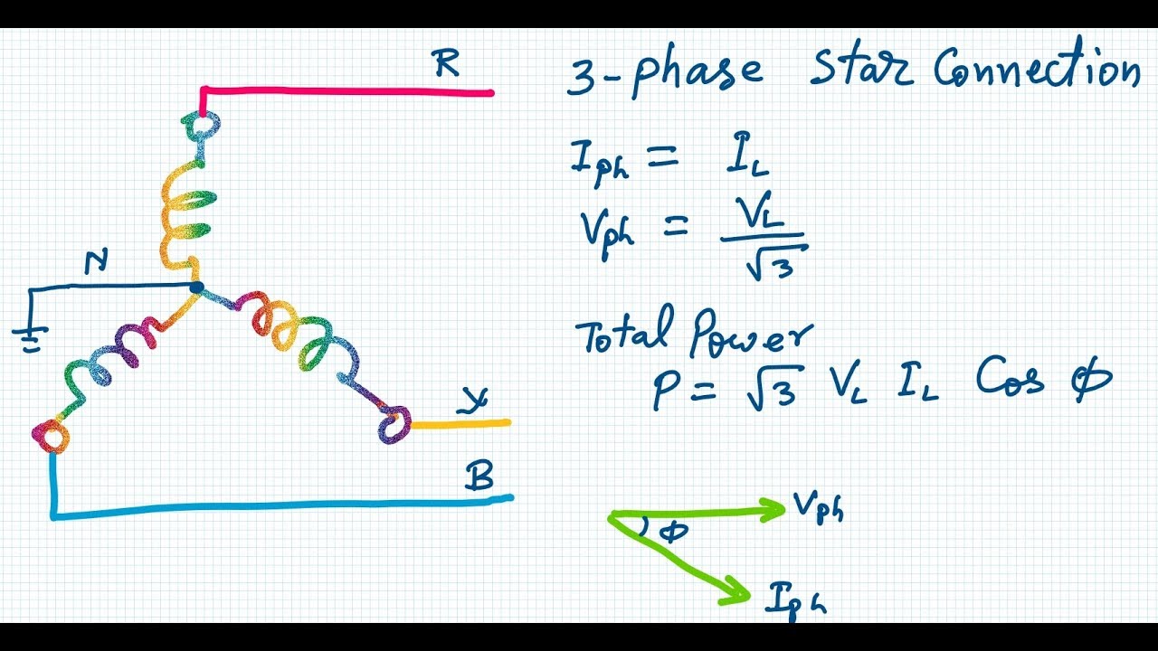
3 Phase Power Equations Rms - Tessshebaylo

Three-phase voltage source inverter. With two possible positions of